An engineering drawing is a subcategory of technical drawings. The purpose is to convey all the information necessary for manufacturing a product or a part.
工程图使用标准化语言和符号。这使得理解图纸简单,几乎没有个人解释的可能性。
So let’s look at the different line and view types you will come across in the engineering discipline.
The Purpose of Engineering Drawings
如前所说,中欧ical drawing hasall the information for manufacturing a part or welding and building an assembly. The info includes dimensions, part names and numbers, etc. So once a manufacturing engineer gets the drawing, he can start the production process without a second thought.
首先,我们必须暂停一秒钟,并在这里向我们自己的客户致辞,以避免混淆。您提交的图纸instant pricing and manufacturingin our system do not need any of this. The same applies to 3D models. CAD files and drawings madeaccording to our design tips包括所有制造产品的必要信息。我们唯一要求图纸的时间是您是否要指定公差。
仍然,knowing all the rules and basics of formatting is an absolute must in the industry传统的制造企业仍然需要d detailed drawings.
如何制作图纸?
几十年前,您将不得不坐在一个覆盖着不同规模,尺子,卡钳等论文的绘图板上。
为什么?因为大多数机械都使用CNC系统,这些系统可以直接从文件中读取信息并相应地生成切割程序。Manbetxios手工制作的图纸只会为制造工程师添加大量手动工作。
So, we are left with only one option really – every engineer should useCAD (computer aided design) software because of its many advantages.
You can, of course, use CAD for making drawings from scratch. But the easier option is to first make a 3D model and create the drawings from that, as the programs generate the views with only a few clicks. All you need to do is add the dimensions. Having models also makes updating the drawings for revisions simple.
工程图的基本组件
Let’s see what makes up an engineering drawing. A single drawing includes many elements with quite a few variations to each of them. So let’s take a closer look here.
不同类型的线
Not every line on an engineering drawing is equal. The different options make it possible to show both visible and hidden edges of a part, centre lines, etc.
The most common is a continuous line, also known as a drawing line. This represents the physical boundaries of an object. Put simply, these lines are for drawing the objects. The line thickness varies – the outer contour uses thicker lines and inner lines are thinner.
Hidden lines can show something that would not be otherwise visible on the drawings. For example, hidden lines may show the length of an internal step in a turned part without using a section or a cutout view (we explain both later).

Centre lines are used to show hole and the symmetric properties of parts. Showing symmetricity can reduce the number of dimensions and make the drawing more eye-pleasing, thus easier to read.
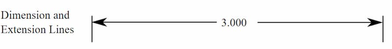
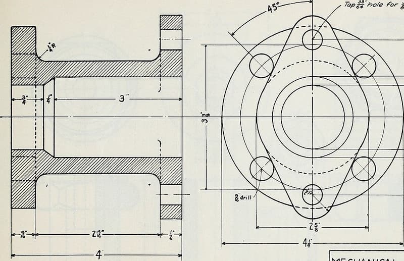
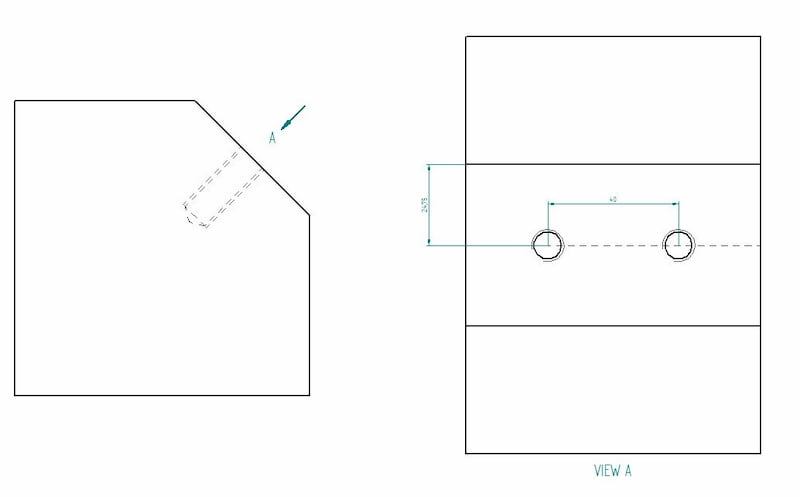
扩展线注释正在测量的内容。尺寸线在延伸线和顶部(或内部,如上图中的内部)之间具有两个箭头。
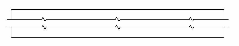
断路线表明视图已被打破。如果您的零件长3000毫米,宽10毫米,具有对称属性,则使用突破可以提供所有信息,而无需使用太多空间。
虽然是向人们提供信息的好方法CNC machines need full views in order to cut the parts. Otherwise, the manufacturing engineer has to reconstruct the whole part from the measurements.
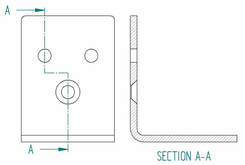
使用切割视图时,切割平面线显示了切口的轨迹。Manbetxios在这里,您可以看到A-A切割线将两种类型的孔都带入视图。Manbetxios
Types of Views
因此,让我们仔细研究制造图中经常存在的不同类型的视图。每个都有一定的目的。请记住,添加视图应遵循与尺寸相同的逻辑 - 包括尽可能少的和尽可能多的逻辑。
A tip for good engineering practice – only include a view if it contributes to the overall understanding of the design.
等距视图
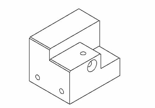
等距图纸显示部分three-dimensional. All the vertical lines stay vertical (compared to front view) and otherwise parallel lines are shown on a 30-degree angle.
The lines that are vertical and parallel are in their true length. Which means you can use a ruler and the scaling of the drawing to easily measure the length straight from a paper drawing, for example. The same does not apply to angled lines.
从透视视图中区分等距视图很重要。观点是一种艺术观点,它代表了眼睛看来的对象。工程师忠于尺寸,而不是幻觉。
Orthographic View
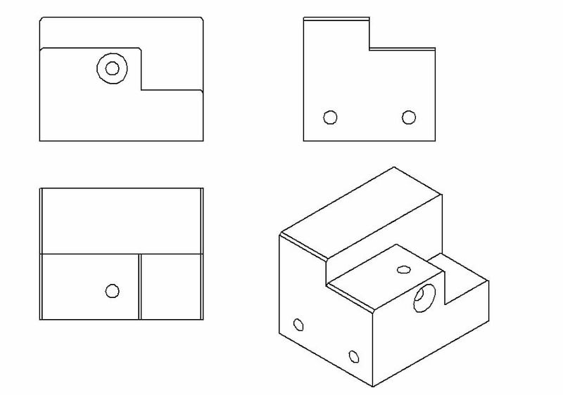
This is the bread and butter of an engineering drawing. An orthographic view or orthographic projection is a way of representing a 3D object in 2 dimensions.
Thus, a 2D view has to convey everything necessary for part production. This kind of representation allows avoiding any kind of distortion of lengths.
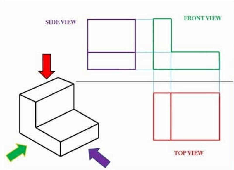
传达所有信息的最常见方法是通过在多视图图中使用三种不同视图:
- Front view
- Top view
- Side view
It may be possible that some additional views are necessary to show all the info. But again, less is more.
The positioning of the views differs a bit regionally. For example, look at the image below to compare the US and ISO layouts.
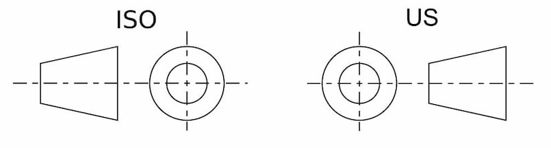
The one on the left is called first-angle projection. Here, the top view is under the front view, the right view is at the left of the front view, etc. The ISO standard is primarily used in Europe.
在右边,您可以看到第三个角度投影。正确的视图位于右侧,前视图顶部的顶视图等等。该系统在美国和加拿大特别受欢迎。
Flat Pattern
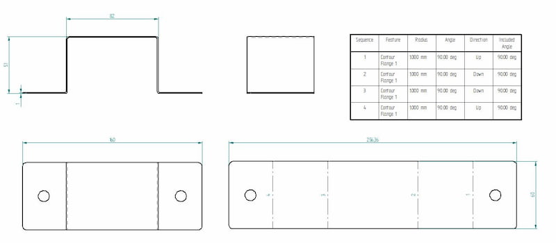
If you are making a folded sheet metal part, do not forget to add a flat pattern view. The cutting job comes before bending. When it comes to our customers, the easiest way is just toupload a STEP file没有任何伴随的图纸。
Get your metal fabrication quote in seconds
 引用几秒钟
引用几秒钟-
Short lead times
-
交付Fractory
创建平坦的图案视图通常很简单。请注意,在CAD中制作钣金零件时,您正在使用钣金环境。您可以选择“生成平坦的图案”,您可以轻松地添加到主图纸中。
If you are using the standard part environment, the same option is not available. Still, many CAD programs have the possibility to convert a standard part into sheet metal if the part properties correspond to sheet metal (e.g. uniform thickness, inside radius, etc.).
Section View
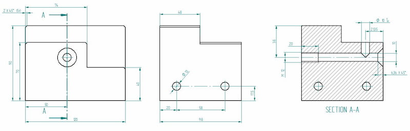
A section view can easily display some of the part features that are not evident when looking just from the outset. Cross section is the preferred option compared to hidden lines as it brings more clarity. The cross hatching feature is and indicator for cross sectional views.
Cutout View
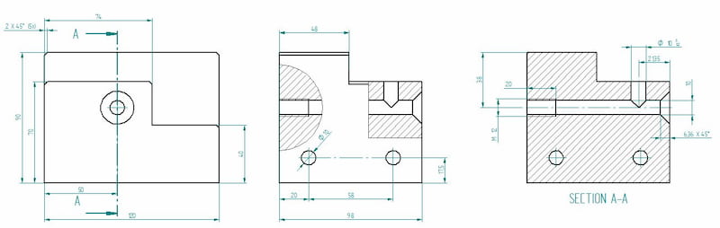
This is the same image we used for illustrating the section view. With one slight difference – the side view includes cutouts. Cutouts can reduce the number of different views on a single drawing.
Thus, we could easily delete the section view and add all the necessary dimensions to cutouts.
Detail View
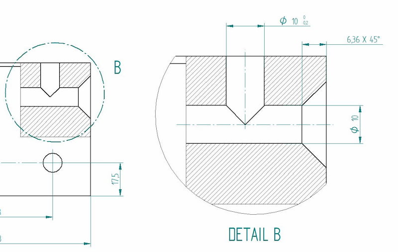
The detail view gives us a close-up of a selected section of a larger view. This can be especially useful if an otherwise large part includes many important dimension in a small area. Using the detail view improves the readability of these measurements.
辅助视图
拼字视图代表非水平或垂直的平面。它有助于显示倾斜的表面而不会失真。
Dimensions
As said before, new CNC machines are actually able to read the dimensions straight from the lines. But a traditional manufacturing drawing shows all the necessary dimensions for producing the parts.
The keyword here is necessary.Avoid using the auto-dimensioning featurethat a lot of CAD programs offer because they tend to show everything they can find. For a beginner, it may seem like adding it all ensures that no mistakes can be made.
Actually, it can result in a confusing web of measurements that is left for the manufacturing engineer to untangle. Also, adding all dimensions you can find makes it hard to pinpoint which ones are the most important.
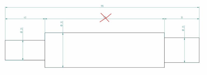
The image above shows a shaft with all the measurements. In reality, it creates a closed system whereby the manufacturer cannot guarantee all these dimensions 100%. Therefore, you have to determine the most important ones. In our case, we chose the end steps to be more important than the length of the central part. Thus, we should delete the 120 mm dimension.
One crucial bit of information that is missing from CAD models isgeometric dimensioning and tolerancing (GD & T). For example, when looking to produce a shaft for a bearing system,limits and fitsare of high importance. The right dimensions can guarantee a longer lifetime with less maintenance.
While you can fetch all the dimensions automatically by clicking themeasure按钮,添加engineering tolerances需要手动动作。
因此,添加具有下限和上限类别的尺寸仍然很重要。关于分裂的服务,我们要求您用这些参数包装一个单独的图纸。请注意,您不必提供整个尺寸 - 如有必要,仅包括工程图上的单个孔的公差。
Information Blocks
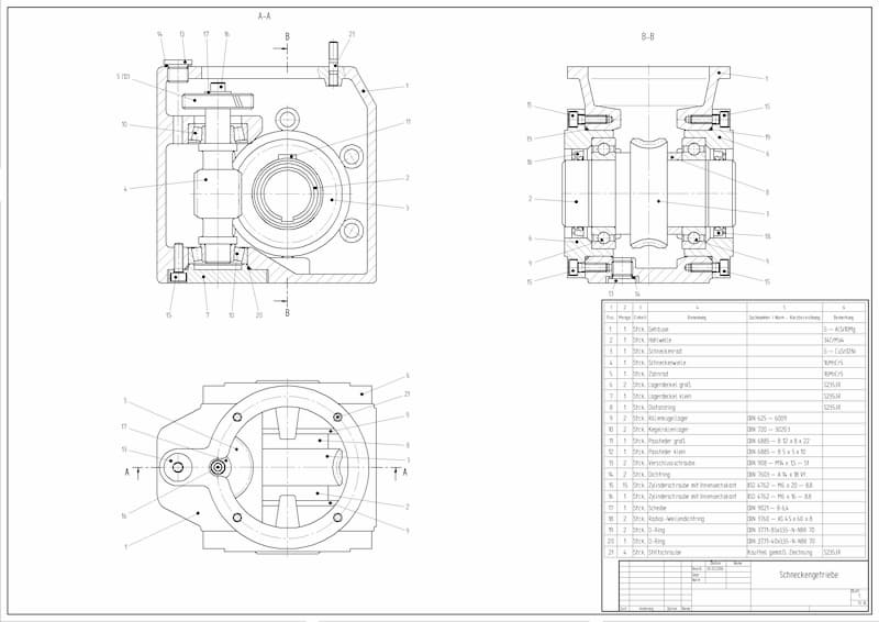
The little boxes in the bottom right corner show additional information. Thetitle block包括作者的姓名,零件名称,零件号,数量,涂料,比例等。那里可能还有更多信息,但标题块之间的块在不同的公司之间差异很大。
Information blocks also include a bill of materials, or BOM for short. These blocks list all the components used in the assembly, along with additional information like quantities, part names, etc.
Assembly Drawings
许多工程师的图纸犯了一个错误,即试图在组装图中包含有关每个部分的所有信息。为了避免这种情况,请记住创建过程中这些工程图纸的目的 - 它们必须使组装变得容易。
爆炸的视图, section views, numbered parts, general dimensions, cutouts, detail views (or close-ups) are all tools you can use to achieve this goal.
It should be clear where each part goes and how it is attached – whether it needs welding, bolted connections, riveting or something else. The bill of materials is there to help you, so make sure the information available there is correct regarding part numbers, names and quantities.
Keeping everything above in mind will help you create assembly drawings that make life easier on the shop floor. A piece of great advice I once received goes like this – keep the thinking in the drawing-room. Avoiding multiple interpretation possibilities at later steps will significantly decrease the number of errors.
What Does the Future Hold?
Engineering drawings are still a big part of an engineer’s job. All in all, making them contributes to about 20% of a design engineer’s work time.
We at Fractory are trying to save this time by automating the reading of 3D models for production. This leaves engineers with the task of producing assembly and GD&T drawings only. The purpose is to keep the focus on engineering better products.
工程社区将这一运动视为一种新趋势。但是,众所周知,将整个行业提高到新标准需要大量时间。因此,如果您仍将生产外包给需要图纸的制造公司,则至少必须了解基础知识。
Leaving room for interpretation creates a situation where your idea may not be executed as planned. And there is nobody else to blame but the author.
So consider this stage of the product development process as an integral part that requires thinking along. Keep the thinking in the drawing-room.
")